
Engineering Data Engineer Data Specifications Dimensions Knowledge Theory

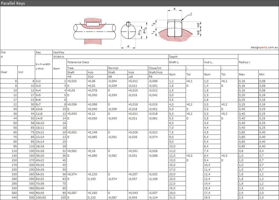
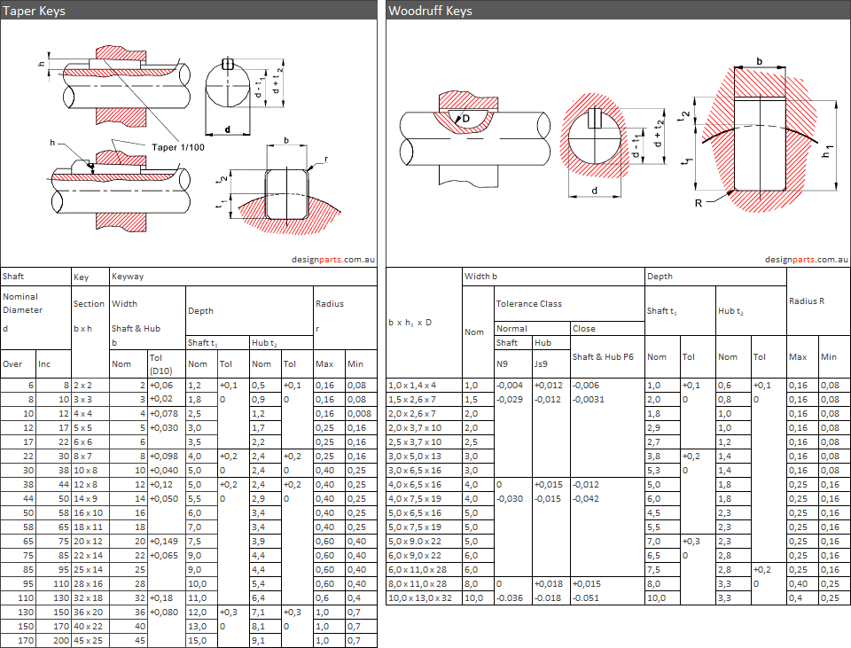
. shaft keys parallel keys woodruff tapere keys tapered keys

.blt belts pulley pulleys chain chains sprocket sprockets gates hitachi chains

|
Roller Chains
|
|||||||||||||||||||||||||||||||||||||||||||||||||||||||||||||||||||||||||||||||||||||||||||||||||||||||||||||||||||||||||||||||||||||||||||||||||||||||||||||||||||||||||||||||||||||||||||||||||||||||||||||||||||||||||||||||||||||||||||||||||||||||||||||||||||||||||||||||||||||||||||||||||||||||||||||||||||||||||||||||||||||||||||||||||||||||||||||||||||||||||||||||||||||||||


Drive Couplings A coupling is used to connect two in-line shafts to allow one shaft (driver) to drive the second shaft(driven) at the same speed. A coupling can be rigid or, more normally, it can be flexible allowing relative radial, axial or angular movement of the two shafts. Unlike the clutch the coupling transmission is not designed to engage-disengage as a normal operation
|


|
Springs Introduction A Spring is an engineering component which when deflected by a force tends to return to its unloaded shape. Ideally the energy input to cause the deflection is usefully recovered. Springs are mechanical components designed to store mechanical energy, working on the principle of flexible deformation of material. Springs constitute one of the most widely used group of components in mechanical engineering. When designing and/or selecting metal springs consideration should be given to material, manufacturing process, heat treatment, dynamic properties, elastic properties, strength, fatigue, shock, stability, surging etc etc. Spring types include: Helical Compression Springs Helical Extension Springs Helical Torsion Springs Coil Springs Disc Springs Leaf Springs Spiral Springs Elastomer Springs Spring Materials Solid springs made from elastomers are not covered
on this page. This page covers materials used for making metal
springs which mainly include helical compression, tensile, and
torsion springs. Leaf springs and disc spring materials
properties may be identified in the more general notes. The
notes also concentrate more on the carbon steel and alloy steel
grades rather than the non-ferrous grades. Future updates will
include more comprehensive information
Springs are manufactured by hot or cold working
processes. The process depends on the section of the material,
the spring index (C= D/d) and the properties required. Reference Standard Notes BS EN 10270-1:2001 ..Steel wire for mechanical
springs. Patented cold drawn unalloyed spring steel wire
A typical wire designation would be "Spring wire BS
EN 10270-1-SH -3,60 ph.
The FD,FDCrV, and FDSiCr (Static) Grades have a
size range of 0,5 to 17,00mm This is the most widely used of
all spring materials for small springs because it is the
toughest. It has the highest strength tensile and
can withstand higher stresses under repeated loading conditions
than any other spring material. It can be obtained in diameters
from 0,12 to 3mm. It has a usable temperature range from 0 to
120oC This is a general purpose spring
material used for spings where the cost of music wire is
prohibitive and for sizes outside the range of music wire. This
material is not suitable for shock or impact loading. This
material is available in diameters from 3 to 12mm.
The temperature range for this material is 0 to 180 oC..Will
not generally change dimensions under heat. Can be
plated. Also available in square and rectangular sections. This is the cheapest general
purpose spring steel and is should only be used where life,
accuracy and deflection are not too important. This material is
available in sizes 0,8mm to 12mm. It has an operating range 0
to 120oC This is the most popular
alloy spring steel for improved stress, fatigue, long endurance
life conditions as compared to high carbon steel
materials. This material is also suitable for impact and shock
loading conditions. Is available in annealed and tempered sizes
from 0,8mm to 12mm. It can be used for temperatures up to 220
oC. Will not generally change dimensions
under heat. Can be plated. This an excellent spring
material for highly-stressed springs requiring long life and/or
shock loading resistance. It is available in diameters 0,8mm to
12mmm and can be used from temperatures up to 250oC.
Will not generally change dimensions under heat. Can be plated. This is a
corrosion, resisting steel which is unsuitable for sub-zero
conditions. A good
corrosion, acid, heat resisting steel with good strength and
moderate temperatures. Has low stress relaxation. This is a low cost material
which is convenient to form. It is a high conductivity
material. This material has poor mechanical properties. This
metal is frequently used in electrical components because of its
good electrical properties and resistance to corrosion. Popular alloy .Withstands
repeated flexures. This metal is frequently used in electrical
components because of its good electrical properties and
resistance to corrosion. Suitable to use in sub-zero
temperatures. They are much more costly than the
more common stocks and cannot be plated. Generally
will not change dimensions under heat. High elastic and fatigue
strength. Hardenable. They are much more costly than the more
common stocks and cannot be plated. Generally will
not change dimensions under heat. These alloys are corrosion
resistant. They can withstand a wide temperature fluctuation.
The materials are suitable to use in precise instruments because
of their non-magnetic characteristic. They also poses a high
electrical resistance and should not be used as an electrical
conductors. Used mainly in aerospace industry
because of its extremely light weight and high strength. This
material is very expensive, It is dangerous to work as titanium
wire will shatter explosively under stress if its surface is
scored. Size range 0,8 to 12mm. Generally will not
change dimensions under heat. Cannot be plated. Important Note..It is important to note that it is best to obtain springs from specialists suppliers who can provide the correct material for the specific application. If springs are being designed for specific applications then strength values should be obtained from the relevant standards as identified above. Care should be taken to include for fatigue and adverse operating conditions. The notes on this page are for rough spring designs. The material structure , the manufacturing process,
and the heat treatment all have an influence on the strength of
the spring material. The strength of spring materials vary
significantly with the wire size such that the strength of a
selected spring material cannot be determined without knowing
the wire size. The standards identified all list the material
strengths against the wire sizes. Sut = A / dm The table below provides some typical values for
the above variables..
In calculating the spring parameters the torsional yield strength (S ys ) is used. The relationship between the torsional yield strength and the ultimate strength Sut can be approximated with a range as follows. 0,35 Sut =< S ys =< 0,52 Sut Music wire and hard drawn steel wire have an
approximate relationship S ys = 0,45 Sut Modulus Of Rigitity values Typical Values for The modulus of Rigidity for different Spring materials are listed below
A helical spring is a spiral wound wire with a constant coil diameter and uniform pitch. The most common form of helical spring is the compression spring but tension springs are also widely used. . Helical springs are generally made from round wire... it is comparatively rare for springs to be made from square or rectangular sections. The strength of the steel used is one of the most important criteria to consider in designing springs. Most helical springs are mass produced by specialists organisations. It is not recommended that springs are made specifically for applications if off-the-shelf springs can be obtained to the job.
Nomenclature
Note: metres (m) have
been shown as the units of length in all of the variables above
for consistency. In most practical calculations
milli-metres will be more convenient.
Spring Index The spring index (C) for helical springs in a measure of coil curvature ..
For most helical springs
C is between 3 and 12 Spring Rate Generally springs are designed to have a deflection proportional to the applied load (or torque -for torsion springs). The "Spring Rate" is the Load per unit deflection.... Rate (N/mm) = F(N) / δ e(deflection=mm)
Spring Stress Values For General purpose springs a maximum stress value of 40% of the steel tensile stress may be used. However the stress levels are related to the duty and material condition (ref to relevant Code/standard). Compression Springs- Formulae
a)
Stress
Consider a compression spring under an axial force F. If a section through a single wire is taken it can be seen that, to maintain equilibrium of forces, the wire is transmits a pure shear load F and also to a torque of Fr.
The stress in the wire due to the applied load =
This equation is simplified by using a traverse shear distribution factor K d = (C+0,5)/C.... The above equation now becomes.
The curvature of the helical spring actually results in higher shear stresses on the inner surfaces of the spring than indicated by the formula above. A curvature correction factor has been determined ( attributed to A.M.Wahl). This (Wahl) factor K w is shown as follows.
This factor includes the traverse shear distribution factor K d.. The formula for maximum shear stress now becomes.
A table relating KW to C is provided below
b) Deflection The spring axial
deflection is obtained as follows.
Replacing T= FD/2, l = πDn, A = πd2 /4 The formula becomes.
Using Castiglianos theorem to find the total strain energy....
Substituting the spring index C for D/d The formula becomes....
In practice the term (1 + 0,5/C2)
which approximates to 1 can be ignored
In practice the term (C2
/(C2
+ 0,5)) which approximates to 1 can be ignored Compression Spring End Designs The figure below shows
various end designs with different handing. Each end
design can be associated with any end design. The plain ends
are not desirable for springs which are highly loaded or for
precise duties.
The table below shows
some equations affected by the end designs...
Helical Extension Springs The formulae provided for
the compression springs generally also apply to extension
springs.
Extension Spring Initial Tension An Extension spring is sometimes tightly wound such that it is prestressed with an initial stress τ i . This results in the spring having a property of an initial tension which must be exceeded before any deflection can take place. When the load exceeds the initial tension the spring behaves according the the formulae above. This relationship is illustrated in the figure below
The initial tension load can be calculated from the formula.... T i = π τ i d 3/ ( 8 D) Best range of of Initial Stress (τ i) for a spring related to the Spring Index C = (D/d)
If the coils in a tension
spring are not tightly wound, there is no initial tension and
the relevant equations are identical to those for the spring
under compression as identified above.
Helical Compression Springs (Rectangular Wire)
Spring Rate and Stress
Conical Helical Compression Springs These are helical springs
with coils progressively change in diameter to give increasing
stiffness with increasing load. This type of spring has the
advantage that its compressed height can be relatively small. A
major user of conical springs is the upholstery industry for
beds and settees.
Allowable Force on
Spring...
Disc Springs A disc spring is a
conical shell spring which is loaded along its axis. Disc
springs can used as single or multiple units. When stacked in
multiple units they can be stacked in series to give a low
stiffness value or in parallel to give a higher stiffness value.
By varying the size and the stacking arrangements an extremely
wide variation in operating parameters can be achieved.
Parallel Stacked springs
(n springs)..For a given force the spring deflection will be
(1/n) x the deflection of a single spring. The stress
experienced by each spring will be 1/n the stress experienced by
the single spring. (friction must be considered when loading is
constantly changing )
Nomenclature
Factors The factors are calculated as follows.
Springs With Contact Surfaces Some of the springs in group 2 and all of the springs in group 3 are manufactured with contact surfaces to enable better load bearing. These flats provide improved contact between springs and they also reduce the outside diameter. A consequence of the
altered geometry is that higher forces are generated. To
compensate for this undesirable effect the thickness of the
spring is reduced from t to t'.
A factor K4 is provided to allow for the different operating characteristics for disc springs with contact surfaces.
If the disc spring has no contact
surfaces the K4
= 1 Spring Force For Goup 1 and Group 2 disc springs without contact surfaces (see note below) K4 = 1 The force at a given disc
spring deflection is obtained by the formula below. This is
for springs with no contact surfaces
For springs Group 3 disc spring with contact surfaces the formula below is more accurate.
When considering springs with contact
surfaces. Use the factor K4
as calculated below and use t' instead of t and use h' = H - t'
Spring Stresses The stresses in a disc
spring at four critical locations 1,2,3,4 see sketch for
positions are shown below _-ve values are compressive stresses
and +ve values are tensile stresses)
Spiral / Clock Springs A spiral spring consists of a strip or wire wound
in a flat spiral . This is subject to a
torque to produce an angular deflection.
A typical spiral spring is a clock spring Nomenclature
Note: metres (m) have been shown as the units of
length in all of the variables above for consistency.
In most practical calculations milli-metres will be more
convenient.
The spring rate k is defined on this webpage as the torque (Nm)per unit angular deflection (θ ).
length of Strip
Spring Rate
Spring sureface stress
Leaf Springs Leaf Springs are widely
used in the automobile and railway industries for suspension
applications. The simplest variation is the single beam
spring. The more normal application is the laminated (multiple)
leaf spring which provides a more efficient stress
distribution..
Laminated leaf springs have the following characteristics
Nomenclature
There are two primary variations the cantilever spring and the simply supported beam..
Multiple leaf springs Considering a cantilever type leaf spring, the stress distribution is related to the distance from the load point. σ = 6Fx / bt2 If (x/b) is constant along beam, of constant thickness t, then the stress level will be constant and the most efficient spring will result. If x/b is constant then a triangular shaped spring results. The multileaf spring is designed to provide a constant stress level along the spring length as it is designed to be equivalent to a triangular spring as shown below.
For this spring the maximum stress( which ideally is constant along the spring) is and the stiffness are as follows..
These equations apply to the quarter elliptic spring as shown below
The relevant equations for the semi-elliptic spring as shown below are
Torsion Springs Springs used to apply torque or store rotational energy are generally called torsion or double torsion springs. Torque by definition is a force that produces rotation. A torsion spring exerts a force (torque) in a circular arc, and the arms rotate about the central axis. The stress is in bending, not in torsion. It is customary to specify torque with deflection or with the arms at a definite position. Torsion bar The torsion bar is the simplest form or torsion
beam. It comprises a solid or hollow bar which is
stressed in torsion within its elastic limit.
Nomenclature
Solid Bar
Solid Bar
A typical torsion helical spring is shown
below. There are a wide variety of coil end configurations to
suit different applications and a torsion spring is usually
positioned on a shaft. The coils are usually close wound as are
tension springs but they generally do not have any initial
tension unlike tension springs.
Note: metres (m) have been shown as the units of length in all of the variables above for consistency. In most practical calculations milli-metres will be more convenient. Torsion Spring Formulae The spring stress concentration factors Ki =
The maximum bending stress is at the inner fibre of the coil and equals
The angular spring rate ka =
Torsion springs are often used over shafts. It is important that the spring inside diameter, when fully loaded is no t equal to, or less than the shaft diameter. If this happens the spring will fail. The inside diameter of the loaded tension spring is
Spring Fatigue Note: Components which are subject to continuously cyclic loading often fail prematurely as a result of fatigue. The worst fatigue loading regimes are loads which continuously reverse from negative (compressive) loading to positive (tensile) loading in a cyclic manner. Reference fatigue loading notes Fatigue Index As springs are often used under continuously fluctuating loading conditions it is necessary to consider fatigue loading and stress concentration factors. Helical springs are never used under conditions of load reversals. They are either normally in tension or normally in compression. In addition springs are often prestressed as part of the forming process or/and preloaded, thus preventing the stress from being zero. These factors mitigate, to some extent, the fatigue loading conditions. All spring subject to continuous fluctuating load are candidates for fatigue failure. Typical springs are
Nomenclature
Fatigue Notes The normal shear stress condition experienced be a spring subject to continuous fluctuating loading is as shown below
The force amplitude and mean value are calculated as
The resulting alternating and mean stresses are
For springs the safety factor for torsional endurance life is
Experimental results have proved that for spring steel the torsional endurance limit is not directly related to size, tensile strength, or material for wires under 10mm diameter. The resulting value from experiments has been determined as S'se = 310 MPa for unpeened springs and 465 MPa for peened springs S'sa = 241 MPa for unpeened springs and 398 MPa for peened springs S'sm = 379 MPa for unpeened springs and 534 MPa for peened springs These values include all modifying factors except for the reliability factor. ref Fatigue modifying factors That is Se = CrS'eFor springs subject to low cyclic /static loading the safety factor for torsional yielding is
It is generally safe to use a torsional yield strength of 40% of the ultimate tensile strength i.e Ssyof 0,4Sut ref notes Spring MaterialsIf the spring applications between 103 and 106 cycles of variation a modified torsional shear strength ( Sfs )can be used to determine the safety margin.
Ssf is the modified shear fatigue strength. This can be determined approximately if the endurance limit( S'se ) and the fatigue strength at 103 cycles ( S'sl ) are available ref High cycle fatigue strength The fatigue design of springs generally involves one of a number of failure criterions, as shown below.
The intersect equation for the Goodmans criterion is
The relevant factor of safety is calculated as follows
Spring Stability
It is necessary to check that relatively long
compression springs are not are risk of buckling. If buckling
is a problem it is necessary to incorporate some method of
guiding the spring by placing it in a hole or on a suitable rod.
Just as a column will buckle when the load becomes too large a long compression spring may buckle when the deflection exceeds a certain value. The critical deflection is given by th e following equation.
Table showing α for different end
conditions
Absolute stability Absolute stability occurs when C'2 /λeff2 is greater than unity. The condition for absolute stability is therefore.
For more detailed notes refer to Surging of SpringsThe equation for the lowest natural frequency of a compression spring located between two flat plates is..
Forcing frequencies near the above lowest natural frequency and at whole multiples (2,4,6...) of this frequency. Helical Spring Surge / Natural Frequency If a spring which is subject to a vibratory motion which is close to its natural frequency the spring can start to surge. This situation is very undesireable because the life of the spring can be reduced as excessive internal stresses can result. The operating characteristics of the spring are also seriously affected. For most springs subject to low frequency vibrations surging is not a problem. However for high frequency vibrating applications it is necessary to to ensure, in the design stage, that the spring natural frequency is 15 to 20 or more times the maximum operating vibration frequency of the spring. Nomenclature
Note: metres (m) have been shown as the units of length in all of the variables above for consistency. In most practical calculations milli-metres will be more convenient. Generally springs are designed to have a deflection proportional to the applied load (or torque -for torsion springs). The "Spring Rate" is the Load per unit deflection.... Rate (N/mm) = F(N) / δ e(deflection=mm)
Natural Frequency of a Loaded spring System Consider a mass M supported on a weightless spring with a spring rate k is illustrated below
This system has a natural frequency as shown below.
This frequency is the lowest natural frequency and is the most important natural frequency. The spring , however not weightless and thus it has vibration characteristics of its own. Vibration effects within the spring and the associated frequencies are found by examinging a small element of the spring in harmonic motion. Surge / Natural frequency of spring For more detailed notes refer to webpage Simple Harmonic Motion Consider a spring below subject to a vibration amplitude u at a circular frequency ω
Consider a small element of the spring comprising dn coils. The density of the spring material is ρ and the length of the wire in the element is π.D.dn. If the wire diameter is d then the element has a mass
For a vibration amplitude u at a circular frequency ω and at any axial location from coil n = 0 to coil n = na the inertial force amplitude is as follows.
The spring rate k for a helical spring is derived on webpage Helical Springs as ..
In practice the term (1 + 0,5/C2) which
approximates to 1 can be ignored For the purpose of this analysis this is transformed to
This equation represents the force for na
active coils .
Equating the forces on the spring element to zero the equation below is derived.
This equation is solved using the equation. u = A sin(c.n) + B cos(c.n)A and B are arbitrary constants.
u = 0 occurs at coil 0 Resulting in the solution B = 0 and cos(c.na) = 0 from which c.na = a.π / 2 ( a= 1,3,5 .....) This results in a set of natural(surge)frequencies
as follows..
For the important fundamental natural frequency,
this can be simplified to..
Import Note : The above analysis relates to a spring with one end against a flat surface and the other end free. The fixed.. fixed case i.e a spring located between and in full contact with two plates results in similar solutions where a = 2, 4, 6......This is also applicable to a spring with one end fixed and against a plate and the other end driven with a sin-wave motion. The fundamental surge frequency resulting from these scenarios are
|
||||||||||||||||||||||||||||||||||||||||||||||||||||||||||||||||||||||||||||||||||||||||||||||||||||||||||||||||||||||||||||||||||||||||||||||||||||||||||||||||||||||||||||||||||||||||||||||||||||||||||||||||||||||||||||||||||||||||||||||||||||||||||||||||||||||||||||||||||||||||||||||||||||||||||||||||||||||||


